BBBのPWMSSモジュールの使い方
概要
BeagleBone Blackに搭載されているAM335xのPWMSS(Pulse-Width Modulation Subsystem)を使用する方法について説明する。
kernel 4.19.94-ti-r42を前提とする。
AM335xには、3個のPWMSSが搭載されている。PWMSSはモードによって以下の機能を提供する。クロックは100MHzとなっており、DMTimerよりも高速な処理が必要な場合に用いることが出来る。
- eHRPWM
PWM信号の生成。タイマーは16bitで、出力A/Bの2本。他のPWMSSと同期を取ることも可能。
- eCAP
時間計測、所定周波数の発生。タイマーは32bitで、入出力は1本。
タイマーのラップアラウンド時に信号を発生させることでPWMを発生する事も可能。
- eQEP
2Phaseロータリーエンコーダー(基準位置信号対応可)のデコード、ポジション、速度検出。
それぞれの機能で入出力ピンが異なっており、それらがマルチプレクサを介してヘッダーに出ている為、機能ごとに分けて説明する。
機会があれば追々調べて行こうと思うが、差し当たり当方で使いたかったeCAP機能について調べた結果を以下に示す。
詳細についてはTexas Instruments提供のAM335x and AMIC110 Sitara Processors Technical Reference Manualを参照の事。
設定方法
ubootの設定
BBBの場合、ピンヘッダに入出力ピンが出ており、dtbの設定で割り当てを何通りか変更できるため、どのピンを使用するかを予め検討しておく必要がある。
dtbファイルで必要な入出力ピンを有効にしておく。あるいは、一時的にであれば、universal capeをenableにしておき、config-pinコマンドでtimerに割り当てる事でも設定可能(だとおもう)。
以下に、関連するMux設定の抜粋を示す。詳細はBBBのリッファレンスマニュアルを参照の事。
eHPWM
| PIN | OFFSET
44e10800+ | PROC | NAME | MODE0 | MODE1 | MODE2 | MODE3 | MODE4 | MODE5 | MODE6 | MODE7 |
|---|
| P8.13 | 24h | T10 | EHRPWM2B | gpmc_ad9 | lcd_data22 | mmc1_dat1 | mmc2_dat5 | ehrpwm2B | | | gpio0[23] |
| P8.14 | 28h | T11 | GPIO0_26 | gpmc_ad10 | lcd_data21 | mmc1_dat2 | mmc2_dat6 | ehrpwm2_tripzone_in | | | gpio0[26] |
| P8.17 | 2ch | U12 | GPIO0_27 | gpmc_ad11 | lcd_data20 | mmc1_dat3 | mmc2_dat7 | ehrpwm0_synco | | | gpio0[27] |
| P8.19 | 20h | U10 | EHRPWM2A | gpmc_ad8 | lcd_data23 | mmc1_dat0 | mmc2_dat4 | ehrpwm2A | | | gpio0[22] |
| P8.34 | cch | U4 | UART3_RTSN | lcd_data11 | gpmc_a15 | ehrpwm1B | mcasp0_ahclkr | mcasp0_axr2 | | uart3_rtsn | gpio2[17] |
| P8.36 | c8h | U3 | UART3_CTSN | lcd_data10 | gpmc_a14 | ehrpwm1A | mcasp0_axr0 | | | uart3_ctsn | gpio2[16] |
| P8.37 | c0h | U1 | UART5_TXD | lcd_data8 | gpmc_a12 | ehrpwm1_tripzone_in | mcasp0_aclkx | uart5_txd | | uart2_ctsn | gpio2[14] |
| P8.38 | c4h | U2 | UART5_RXD | lcd_data9 | gpmc_a13 | ehrpwm0_synco | mcasp0_fsx | uart5_rxd | | uart2_rtsn | gpio2[15] |
| P8.43 | a8h | R3 | GPIO2_8 | lcd_data2 | | gpmc_a2 | ehrpwm2_tripzone_in | | | | gpio2[8] |
| P8.44 | ach | R4 | GPIO2_9 | lcd_data3 | | gpmc_a3 | ehrpwm0_synco | | | | gpio2[9] |
| P8.45 | a0h | R1 | GPIO2_6 | lcd_data0 | | gpmc_a0 | ehrpwm2A | | | | gpio2[6] |
| P8.46 | a4h | R2 | GPIO2_7 | lcd_data1 | | gpmc_a1 | ehrpwm2B | | | | gpio2[7] |
| P9.14 | 48h | U14 | EHRPWM1A | gpmc_a2 | mii2_txd3 | rgmii2_td3 | mmc2_dat1 | gpmc_a18 | | ehrpwm1A_mux1 | gpio1[18] |
| P9.15 | 40h | R13 | GPIO1_16 | gpmc_a0 | gmii2_txen | rmii2_tctl | mii2_txen | gpmc_a16 | | ehrpwm1_tripzone_input | gpio1[16] |
| P9.16 | 4ch | T14 | EHRPWM1B | gpmc_a3 | mii2_txd2 | rgmii2_td2 | mmc2_dat2 | gpmc_a19 | | ehrpwm1B_mux1 | gpio1[19] |
| P9.17 | 15ch | A16 | I2C1_SCL | spi0_cs0 | mmc2_sdwp | I2C1_SCL | ehrpwm0_synci | | | | gpio0[5] |
| P9.18 | 158h | B16 | I2C1_SDA | spi0_d1 | mmc1_sdwp | I2C1_SDA | ehrpwm0_tripzone | | | | gpio0[4] |
| P9.21 | 154h | B17 | UART2_TXD | spi0_d0 | uart2_txd | I2C2_SCL | ehrpwm0B | | | EMU3_mux1 | gpio0[3] |
| P9.22 | 150h | A17 | UART2_RXD | spi0_sclk | uart2_rxd | I2C2_SDA | ehrpwm0A | | | EMU2_mux1 | gpio0[2] |
| P9.23 | 44h | V14 | GPIO1_17 | gpmc_a1 | gmii2_rxdv | rgmii2_rxdv | mmc2_dat0 | gpmc_a17 | | ehrpwm0_synco | gpio1[17] |
| P9.42A | 164h | C18 | GPIO0_7 | eCAP0_in_PWM0_out | uart3_txd | spi1_cs1 | pr1_ecap0_ecap_capin_apwm_o | spi1_sclk | mmc0_sdwp | xdma_event_intr2 | gpio0[7] |
| P9.42B | 1a0h | B12 | GPIO3_18 | Mcasp0_aclkr | eQEP0A_in | Mcaspo_axr2 | Mcasp1_aclkx | | | | gpio3[18] |
P9.42は2つのGPIOで共有されているので、使用しない方はハイインピーダンス状態としておく必要がある。
eCAP
| PIN | OFFSET
44e10800+ | PROC | NAME | MODE0 | MODE1 | MODE2 | MODE3 | MODE4 | MODE5 | MODE6 | MODE7 |
|---|
| P9.28 | 19ch | C12 | SPI1_CS0 | mcasp0_ahclkr | ehrpwm0_synci | mcasp0_axr2 | spi1_cs0 | eCAP2_in_PWM2_out | pr1_pru0_pru_r30_3 | pr1_pru0_pru_r31_3 | gpio3[17] |
| P9.42A | 164h | C18 | GPIO0_7 | eCAP0_in_PWM0_out | uart3_txd | spi1_cs1 | pr1_ecap0_ecap_capin_apwm_o | spi1_sclk | mmc0_sdwp | xdma_event_intr2 | gpio0[7] |
| P9.42B | 1a0h | B12 | GPIO3_18 | Mcasp0_aclkr | | | | eQEP0A_in | Mcaspo_axr2 | Mcasp1_aclkx | gpio3[18] |
P9.28はデフォルトでHDMIの音声出力に割り当てられているのでHDMIをdisableにしておく必要がある。
P9.42は2つのGPIOで共有されているので、使用しない方はハイインピーダンス状態としておく必要がある。
eCAP1は内部でJ1のUART0_TXに接続されており、cape managerでこのピンは設定を変更する機能が提供されていない為使用できない。従って、BBBで利用できるのはeCAP0とeCAP2の2つとなる。
以下のdtsファイルを作成した。
/dts-v1/;
/plugin/;

/ {
    compatible = "ti,beaglebone", "ti,beaglebone-black";

    /* identification */
    part-number = "BB-eCAP";
    version = "00A0";

    exclusive-use =
        "P9.42",
        "P9.28",
        "eCAP0_in_PWM0_out",
        "eCAP2_in_PWM2_out";

    fragment@0 {
        target = <&am33xx_pinmux>;
        __overlay__ {
            ecap0_gpio: pinmux_ecap0_pins {
                pinctrl-single,pins = <
                    0x164 0x28  /* (IN|PU_DIS|MODE0)=(0 01 000) eCAP0_in_PWM0_out P9.42 */
                >;
            };
            ecap2_gpio: pinmux_ecap2_pins {
                pinctrl-single,pins = <
                    0x19C 0x2c  /* (IN|PU_DIS|MODE4)=(0 01 100) eCAP2_in_PWM2_out_mux1 P9.28 */
                >;
            };
            gpio3_gpio: pinmux_gpio3_pins {
                pinctrl-single,pins = <
                    0x1A0 0x2f  /* (IN|PU_DIS|MODE7)=(1 01 111) gpio3[18], set Hi-Z P9.42 */
                >;
            };
        };
    };


    fragment@1 {
        target = <&ocp>;
        __overlay__ {
            bb_ecap0 {
                compatible      = "bb-ecap";
                pwms            = <&ecap0 0 0 1>;
                pwm-names       = "ECAP0";
                pinctrl-names   = "default";
                pinctrl-0       = <&ecap0_gpio>;
                enabled         = <1>;
                duty            = <0>;
                status          = "okay";
            };
            bb_ecap2 {
                compatible      = "bb-ecap";
                pwms            = <&ecap2 0 0 1>;
                pwm-names       = "ECAP2";
                pinctrl-names   = "default";
                pinctrl-0       = <&ecap2_gpio>;
                enabled         = <1>;
                duty            = <0>;
                status          = "okay";
            };
            bb_ecap0_gpio_helper: ecap0_gpio_helper {
                compatible      = "bone-pinmux-helper";
                pinctrl-names   = "default";
                pinctrl-0       = <&ecap0_gpio>;
                status          = "okay";
            };
            bb_ecap2_gpio_helper: ecap2_gpio_helper {
                compatible      = "bone-pinmux-helper";
                pinctrl-names   = "default";
                pinctrl-0       = <&ecap2_gpio>;
                status          = "okay";
            };
            bb_gpio3_gpio_helper: gpio3_gpio_helper {
                compatible      = "bone-pinmux-helper";
                pinctrl-names   = "default";
                pinctrl-0       = <&gpio3_gpio>;
                status          = "okay";
            };
        };
    };

    fragment@2 {
        target = <&pruss>;
        __overlay__ {
            status          = "okay";
        };
    };
};
一時的にであれば、config-pinコマンドで次のように設定すればよい模様。
PRUから操作する場合はpru_ecapにする必要があるかも。
GPIO3_18については、この場合どういう設定になるのかよくわからないが、GPIOはデフォルトでinputになっているので、特に弄っていなければ、問題はないだろう。
P9.28には、pwmとpwm2という選択肢があるが、pwm2にしないと動作しなかった。どういった違いがあるのかは調べていない。
root@beaglebone:/sys/class/pwm/pwm-6:0# config-pin -l P9.28

Available modes for P9_28 are: default gpio gpio_pu gpio_pd gpio_input spi_cs pwm pwm2 pruout pruin

root@beaglebone:/sys/class/gpio/gpio7# config-pin P9.28 pwm2

Current mode for P9_28 is:     pwm2

root@beaglebone:/sys/class/pwm/pwm-6:0# config-pin -l P9.42

Available modes for P9_42 are: default gpio gpio_pu gpio_pd gpio_input spi_cs spi_sclk uart pwm pru_ecap

root@beaglebone:/sys/class/gpio/gpio7# config-pin P9.42 pwm

Current mode for P9_42 is:     pwm
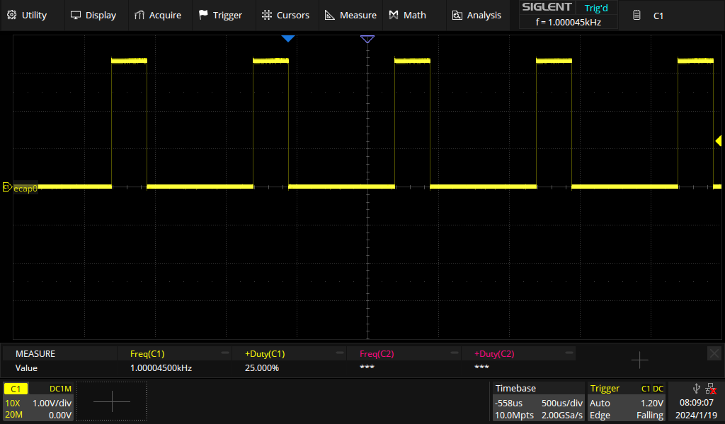
さしあたり、この設定でPWMの出力が出来るかテストする。
eCAP0, eCAP2がどのデバイスツリーに紐づけられているのか、kernel versionによって異なっていたりして明確な資料が見つからないが、
実機を調べると、メモリアドレスとリンク先のデバイス名が一致している模様。
つまり、pwm-0:0がeCAP0、pwm-6:0がeCAP2ということのようだ。
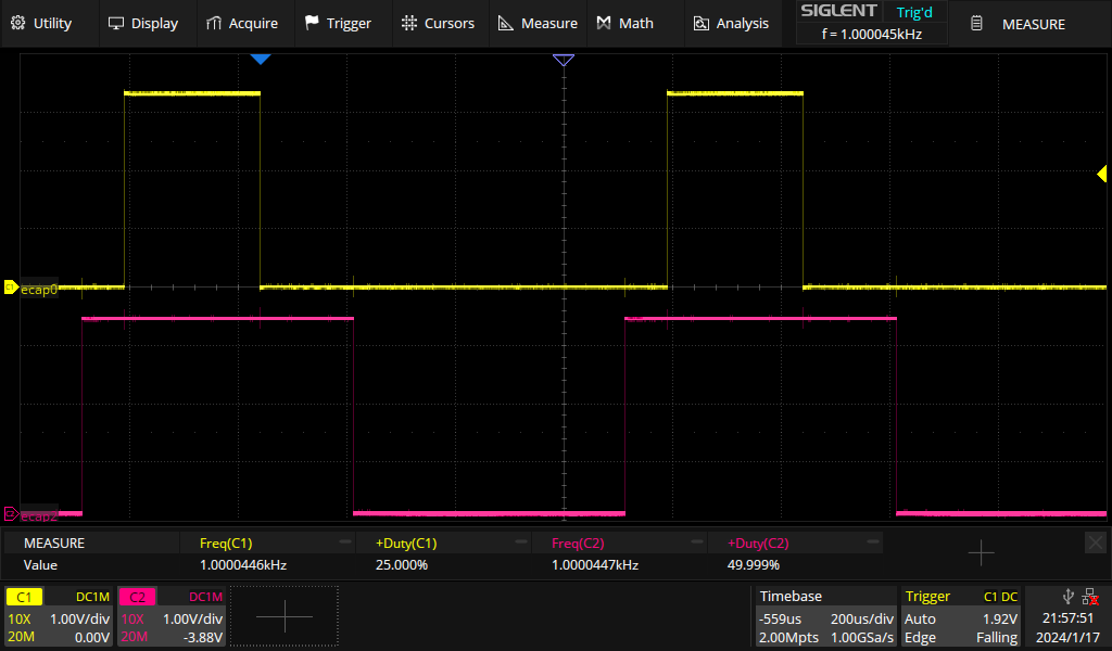
周期はnsec指定、duty cycleは1/10000%で指定する。
この結果右図のような出力が得られた。eCAP0とeCAP2の開始時期は同期していないので毎回ズレるが、レジスタで同期機能を設定すれば同期させることもできるだろう。
root@beaglebone:/sys/class/pwm# ls -l
total 0
lrwxrwxrwx 1 root root 0 Jan 17 13:31 pwm-0:0 -> ../../devices/platform/ocp/48300000.epwmss/48300100.ecap/pwm/pwmchip0/pwm-0:0
lrwxrwxrwx 1 root root 0 Jan 17 13:31 pwm-1:0 -> ../../devices/platform/ocp/48300000.epwmss/48300200.pwm/pwm/pwmchip1/pwm-1:0
lrwxrwxrwx 1 root root 0 Jan 17 13:31 pwm-1:1 -> ../../devices/platform/ocp/48300000.epwmss/48300200.pwm/pwm/pwmchip1/pwm-1:1
lrwxrwxrwx 1 root root 0 Jan 17 13:31 pwm-3:0 -> ../../devices/platform/ocp/48302000.epwmss/48302100.ecap/pwm/pwmchip3/pwm-3:0
lrwxrwxrwx 1 root root 0 Jan 17 13:31 pwm-4:0 -> ../../devices/platform/ocp/48302000.epwmss/48302200.pwm/pwm/pwmchip4/pwm-4:0
lrwxrwxrwx 1 root root 0 Jan 17 13:31 pwm-4:1 -> ../../devices/platform/ocp/48302000.epwmss/48302200.pwm/pwm/pwmchip4/pwm-4:1
lrwxrwxrwx 1 root root 0 Jan 17 13:31 pwm-6:0 -> ../../devices/platform/ocp/48304000.epwmss/48304100.ecap/pwm/pwmchip6/pwm-6:0
lrwxrwxrwx 1 root root 0 Jan 17 13:31 pwm-7:0 -> ../../devices/platform/ocp/48304000.epwmss/48304200.pwm/pwm/pwmchip7/pwm-7:0
lrwxrwxrwx 1 root root 0 Jan 17 13:31 pwm-7:1 -> ../../devices/platform/ocp/48304000.epwmss/48304200.pwm/pwm/pwmchip7/pwm-7:1
lrwxrwxrwx 1 root root 0 Jan 17 13:31 pwmchip0 -> ../../devices/platform/ocp/48300000.epwmss/48300100.ecap/pwm/pwmchip0
lrwxrwxrwx 1 root root 0 Jan 17 13:31 pwmchip1 -> ../../devices/platform/ocp/48300000.epwmss/48300200.pwm/pwm/pwmchip1
lrwxrwxrwx 1 root root 0 Jan 17 13:31 pwmchip3 -> ../../devices/platform/ocp/48302000.epwmss/48302100.ecap/pwm/pwmchip3
lrwxrwxrwx 1 root root 0 Jan 17 13:31 pwmchip4 -> ../../devices/platform/ocp/48302000.epwmss/48302200.pwm/pwm/pwmchip4
lrwxrwxrwx 1 root root 0 Jan 17 13:31 pwmchip6 -> ../../devices/platform/ocp/48304000.epwmss/48304100.ecap/pwm/pwmchip6
lrwxrwxrwx 1 root root 0 Jan 17 13:31 pwmchip7 -> ../../devices/platform/ocp/48304000.epwmss/48304200.pwm/pwm/pwmchip7

root@beaglebone:/sys/class/pwm/pwm-0:0# ls
capture  device  duty_cycle  enable  period  polarity  power  subsystem  uevent
root@beaglebone:/sys/class/pwm/pwm-0:0# echo 1000000 > period
root@beaglebone:/sys/class/pwm/pwm-0:0# echo 1 > enable
root@beaglebone:/sys/class/pwm/pwm-0:0# echo 25000 > duty_cycle
root@beaglebone:/sys/class/pwm/prm-0:0# cd ../pwm-6\:0
root@beaglebone:/sys/class/pwm/pwm-6:0# echo 1000000 > period
root@beaglebone:/sys/class/pwm/pwm-6:0# echo 500000 > duty_cycle
root@beaglebone:/sys/class/pwm/pwm-6:0# echo 1 > enable
eQEP
| PIN | OFFSET | PROC | NAME | MODE0 | MODE1 | MODE2 | MODE3 | MODE4 | MODE5 | MODE6 | MODE7 |
|---|
| P8.11 | h | R12 | GPIO1_13 | gpmc_ad13 | lcd_data18 | mmc1_dat5 | mmc2_dat1 | eQEP2B_in | | | gpio1[13] |
| P8.12 | h | T12 | GPIO1_12 | GPMC_AD12 | LCD_DATA19 | Mmc1_dat4 | MMC2_DAT0 | EQEP2A_IN | | | gpio1[12] |
| P8.15 | h | U13 | GPIO1_15 | gpmc_ad15 | lcd_data16 | mmc1_dat7 | mmc2_dat3 | eQEP2_strobe | | | gpio1[15] |
| P8.16 | h | V13 | GPIO1_14 | gpmc_ad14 | lcd_data17 | mmc1_dat6 | mmc2_dat2 | eQEP2_index | | | gpio1[14] |
| P8.31 | h | V4 | UART5_CTSN | lcd_data14 | gpmc_a18 | eQEP1_index | mcasp0_axr1 | | uart5_rxd | uart5_ctsn | gpio0[10] |
| P8.32 | h | T5 | UART5_RTSN | lcd_data15 | gpmc_a19 | eQEP1_strobe | mcasp0_ahclkx | mcasp0_axr3 | | uart5_rtsn | gpio0[11] |
| P8.33 | h | V3 | UART4_RTSN | lcd_data13 | gpmc_a17 | eQEP1B_in | mcasp0_fsr | mcasp0_axr3 | | uart4_rtsn | gpio0[9] |
| P8.35 | h | V2 | UART4_CTSN | lcd_data12 | gpmc_a16 | eQEP1A_in | mcasp0_aclkr | mcasp0_axr2 | | uart4_ctsn | gpio0[8] |
| P8.39 | h | T3 | GPIO2_12 | lcd_data6 | gpmc_a6 | | eQEP2_index | | | | gpio2[12] |
| P8.40 | h | T4 | GPIO2_13 | lcd_data7 | gpmc_a7 | | eQEP2_strobe | pr1_edio_data_out7 | | | gpio2[13] |
| P8.41 | h | T1 | GPIO2_10 | lcd_data4 | gpmc_a4 | | eQEP2A_in | | | | gpio2[10] |
| P8.42 | h | T2 | GPIO2_11 | lcd_data5 | gpmc_a5 | | eQEP2B_in | | | | gpio2[11] |
| P9.25 | h | A14 | GPIO3_21 | mcasp0_ahclkx | eQEP0_strobe | mcasp0_axr3 | mcasp1_axr1 | EMU4_mux2 | | | gpio3[21] |
| P9.27 | h | C13 | GPIO3_19 | mcasp0_fsr | eQEP0B_in | mcasp0_axr3 | mcasp1_fsx | EMU2_mux2 | | | gpio3[19] |
| P9.41A | h | D14 | CLKOUT2 | xdma_event_intr1 | | tclkin | clkout2 | timer7_mux1 | | EMU3_mux0 | gpio0[20] |
| P9.41B | h | D13 | GPIO3_20 | mcasp0_axr1 | eQEP0_index | | Mcasp1_axr0 | emu3 | | | gpio3[20] |
| P9.42A | h | C18 | GPIO0_7 | eCAP0_in_PWM0_out | uart3_txd | spi1_cs1 | pr1_ecap0_ecap_capin_apwm_o | spi1_sclk | mmc0_sdwp | xdma_event_intr2 | gpio0[7] |
| P9.42B | h | B12 | GPIO3_18 | Mcasp0_aclkr | eQEP0A_in | Mcaspo_axr2 | Mcasp1_aclkx | | | | gpio3[18] |
P9.41, P9.42は2つのGPIOで共有されているので、使用しない方はハイインピーダンス状態としておく必要がある。
PWMSS moduleのenable
PWMSS moduleはデフォルトでdisableになっているので、CM_PER registerのCM_PER_EPWMSSx_CLKCTRLレジスタで有効に設定する必要がある。
この設定を行わないと、PWMSS関連レジスタへのアクセスもBus errorになる。
Offset
0x44E00000 + | Acronym |
|---|
| 0h | CM_PER_L4LS_CLKSTCTRL |
| 4h | CM_PER_L3S_CLKSTCTRL |
| Ch | CM_PER_L3_CLKSTCTRL |
| 14h | CM_PER_CPGMAC0_CLKCTRL |
| 18h | CM_PER_LCDC_CLKCTRL |
| 1Ch | CM_PER_USB0_CLKCTRL |
| 24h | CM_PER_TPTC0_CLKCTRL |
| 28h | CM_PER_EMIF_CLKCTRL |
| 2Ch | CM_PER_OCMCRAM_CLKCTRL |
| 30h | CM_PER_GPMC_CLKCTRL |
| 34h | CM_PER_MCASP0_CLKCTRL |
| 38h | CM_PER_UART5_CLKCTRL |
| 3Ch | CM_PER_MMC0_CLKCTRL |
| 40h | CM_PER_ELM_CLKCTRL |
| 44h | CM_PER_I2C2_CLKCTRL |
| 48h | CM_PER_I2C1_CLKCTRL |
| 4Ch | CM_PER_SPI0_CLKCTRL |
| 50h | CM_PER_SPI1_CLKCTRL |
| 60h | CM_PER_L4LS_CLKCTRL |
| 68h | CM_PER_MCASP1_CLKCTRL |
| 6Ch | CM_PER_UART1_CLKCTRL |
| 70h | CM_PER_UART2_CLKCTRL |
| 74h | CM_PER_UART3_CLKCTRL |
| 78h | CM_PER_UART4_CLKCTRL |
| 7Ch | CM_PER_TIMER7_CLKCTRL |
| 80h | CM_PER_TIMER2_CLKCTRL |
| 84h | CM_PER_TIMER3_CLKCTRL |
| 88h | CM_PER_TIMER4_CLKCTRL |
| ACh | CM_PER_GPIO1_CLKCTRL |
| B0h | CM_PER_GPIO2_CLKCTRL |
| B4h | CM_PER_GPIO3_CLKCTRL |
| BCh | CM_PER_TPCC_CLKCTRL |
| C0h | CM_PER_DCAN0_CLKCTRL |
| C4h | CM_PER_DCAN1_CLKCTRL |
| CCh | CM_PER_EPWMSS1_CLKCTRL |
| D4h | CM_PER_EPWMSS0_CLKCTRL |
| D8h | CM_PER_EPWMSS2_CLKCTRL |
| DCh | CM_PER_L3_INSTR_CLKCTRL |
| E0h | CM_PER_L3_CLKCTRL |
| E4h | CM_PER_IEEE5000_CLKCTRL |
| E8h | CM_PER_PRU_ICSS_CLKCTRL |
| ECh | CM_PER_TIMER5_CLKCTRL |
| F0h | CM_PER_TIMER6_CLKCTRL |
| F4h | CM_PER_MMC1_CLKCTRL |
| F8h | CM_PER_MMC2_CLKCTRL |
| FCh | CM_PER_TPTC1_CLKCTRL |
| 100h | CM_PER_TPTC2_CLKCTRL |
| 10Ch | CM_PER_SPINLOCK_CLKCTRL |
| 110h | CM_PER_MAILBOX0_CLKCTRL |
| 11Ch | CM_PER_L4HS_CLKSTCTRL |
| 120h | CM_PER_L4HS_CLKCTRL |
| 12Ch | CM_PER_OCPWP_L3_CLKSTCTRL |
| 130h | CM_PER_OCPWP_CLKCTRL |
| 140h | CM_PER_PRU_ICSS_CLKSTCTRL |
| 144h | CM_PER_CPSW_CLKSTCTRL |
| 148h | CM_PER_LCDC_CLKSTCTRL |
| 14Ch | CM_PER_CLKDIV32K_CLKCTRL |
| 150h | CM_PER_CLK_24MHZ_CLKSTCTRL |
| CM_PER_PWMSSx_CLKCTRL Register |
|---|
| Bit | Field | Type | Reset | Description |
|---|
| 31-18 | Reserved | R | 0h | |
| 17-16 | IDLEST | R | 3h |
Module idle status.
0x0 = Func : Module is fully functional, including OCP
0x1 = Trans : Module is performing transition: wakeup, or sleep, or sleep abortion
0x2 = Idle : Module is in Idle mode (only OCP part). It is functional if
using separate functional clock
0x3 = Disable : Module is disabled and cannot be accessed
|
| 15-2 | Reserved | R | 0h | |
| 1-0 | MODULEMODE | R/W | 0h |
Control the way mandatory clocks are managed.
0x0 = DISABLED : Module is disable by SW. Any OCP access to module results in an error, except if resulting from a module wakeup (asynchronous wakeup).
0x1 = RESERVED_1 : Reserved
0x2 = ENABLE : Module is explicitly enabled. Interface clock (if not used for functions) may be gated according to the clock domain state. Functional clocks are guarantied to stay present. As long as in this configuration, power domain sleep transition cannot happen.
0x3 = RESERVED : Reserved
|
以下のレジスタは基本的に触る必要は無い。
Offset from:
0x4830_0000
0x4830_2000
0x4830_4000 | Acronym |
|---|
| 0h | IDVER Register |
| 4h | SYSCONFIG Register |
| 8h | CLKCONFIG Register |
| ch | CLKSTATUS Register |
eCAP Functionの動作
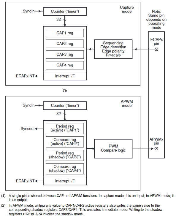
さらに、CaptureモードとAPWMモードがある。
入出力はモードによって決まる。
Capture modeでは入力信号はプリスケーラーで分周した後、立ち上がり、立下りの何れか、若しくは双方を対象にTSCTRレジスタの値がCAP1-CAP4まで順次保存される。
TSCTRレジスタはクロック若しくは同期信号によるフリーランカウンタで、オーバーフロー時はCTR_OVFがセットされる。
計測が完了した際、割込みを発生させることが出来る。CAPxレジスタの時刻を比較する事で、周期若しくは周波数を計算できる。
eCAP Registers
Offset from:
0x4830_0100
0x4830_2100
0x4830_4100 | Acronym |
|---|
| 0h | TSCTR Time-Stamp Counter Register |
| 4h | CTRPHS Counter Phase Offset Value Register |
| 8h | CAP1 Capture 1 Register |
| Ch | CAP2 Capture 2 Register |
| 10h | CAP3 Capture 3 Register |
| 14h | CAP4 Capture 4 Register |
| 28h | ECCTL1 Capture Control Register 1 |
| 2Ah | ECCTL2 Capture Control Register 2 |
| 2Ch | ECEINT Capture Interrupt Enable Register |
| 2Eh | ECFLG Capture Interrupt Flag Register |
| 30h | ECCLR Capture Interrupt Clear Register |
| 32h | ECFRC Capture Interrupt Force Register |
| 5Ch | REVID Revision ID Register |
| TSCTR |
|---|
| Bit | Field | Type | Reset | Description |
|---|
| 31-0 | TSCTR | R/W | 0h | Active 32bit counter register that is used as the capture time-base |
| CTRPHS |
|---|
| Bit | Field | Type | Reset | Description |
|---|
| 31-0 | CTRPHS | R/W | 0h | Counter phase value register that can be programmed for phase lag/lead.
This register shadows TSCTR and is loaded into TSCTR upon either a SYNCI event or S/W force via a control bit.
Used to achieve phase control synchronization with respect to other eCAP and EPWM time-base |
| CAPx |
|---|
| Bit | Field | Type | Reset | Description |
|---|
| 31-0 | CAPx | R/W | 0h |
This register can be loaded (written) by the following.
(a) Time-Stamp (that is, counter value) during a capture event.
(b) Software may be useful for test purposes.
(c) APRD active register when used in APWM mode |
| ECCTL1 |
|---|
| Bit | Field | Type | Reset | Description |
|---|
| 15-14 | FREE_SOFT | R/W | 0h | Emulation Control
0h=TSCTR counter stops immediately on emulation suspend.
1h=TSCTR counter runs until 0.
2h & 3h=TSCTR counter is unaffected by emulation suspend(Run Free).
|
| 13-9 | PRESCALE | R/W | 0h | Event Filter prescale slect
分周比=2*N, 0の場合Disable |
| 8 | CAPLDEN | R/W | 0h | Enable Loading of CAP1 to CAP4 registers on a capture event
0h=Disable
1h=Enable |
| 7 | CTRRST4 | R/W | 0h | Counter Reset on Capture Event 4
0h=Disable
1h=Enable |
| 6 | CAP4POL | R/W | 0h | Capture Event 4 Polarity select
0h=Rising edge
1h=Falling edge |
| 5 | CTRRST3 | R/W | 0h | Counter Reset on Capture Event 3
0h=Disable
1h=Enable |
| 4 | CAP3POL | R/W | 0h | Capture Event 3 Polarity select
0h=Rising edge
1h=Falling edge |
| 3 | CTRRST2 | R/W | 0h | Counter Reset on Capture Event 2
0h=Disable
1h=Enable |
| 2 | CAP2POL | R/W | 0h | Capture Event 2 Polarity select
0h=Rising edge
1h=Falling edge |
| 1 | CTRRST1 | R/W | 0h | Counter Reset on Capture Event 1
0h=Disable
1h=Enable |
| 0 | CAP1POL | R/W | 0h | Capture Event 1 Polarity select
0h=Rising edge
1h=Falling edge |
| ECCTL2 |
|---|
| Bit | Field | Type | Reset | Description |
|---|
| 15-11 | RESERVED | R | 0h | |
| 10 | APWMPOL | R/W | 0h | APWM output polarity select.
This is applicable only in APWM operating mode
0h = Output is active high (Compare value defines high time)
1h = Output is active low (Compare value defines low ti |
| 9 | CAP_APWM | R/W | 0h | CAP/APWM operating mode select
0h = ECAP module operates in capture mode. This mode forces the following configuration. (a) Inhibits TSCTR resets via PRDEQ event. (b) Inhibits shadow loads on CAP1 and 2 registers. (c) Permits user to enable CAP1-4 register load. (d) ECAPn/APWMn pin operates as a capture input.
1h = ECAP module operates in APWM mode. This mode forces the following configuration. (a) Resets TSCTR on PRDEQ event (period boundary). (b) Permits shadow loading on CAP1 and 2 registers. (c) Disables loading of time-stamps into CAP1-4 registers. (d) ECAPn/APWMn pin operates as a APWM outp |
| 8 | SWSYNC | R/W | 0h | Software-forced Counter (TSCTR) Synchronizing.
This provides a convenient software method to synchronize some or all ECAP time bases.
In APWM mode, the synchronizing can also be done via the PRDEQ event.
Note: Selecting PRDEQ is meaningful only in APWM mode.
However, you can choose it in CAP mode if you find doing so useful.
0h = Writing a zero has no effect. Reading always returns a zero
1h = Writing a one forces a TSCTR shadow load of current ECAP module and any ECAP modules down-stream providing the SYNCO_SEL bits are 0,0. After writing a 1, this bit returns to a zero |
| 7-6 | SYNCO_SEL | R/W | 0h | Sync-Out Select
0h = Select sync-in event to be the sync-out signal (pass through)
1h = Select PRDEQ event to be the sync-out signal
2h = Disable sync out signal
3h = Disable sync out sign |
| 5 | SYNCI_EN | R/W | 0h | Counter (TSCTR) Sync-In select mode
0h = Disable sync-in option
1h = Enable counter (TSCTR) to be loaded from CTRPHS register
upon either a SYNCI signal or a S/W force event. |
| 4 | TSCTRSTOP | R/W | 0h | Time Stamp (TSCTR) Counter Stop (freeze) Control
0h = TSCTR stopped
1h = TSCTR free-running |
| 3 | RE-ARM | R/W | 0h | One-Shot Re-Arming Control, that is, wait for stop trigger.
Note: The re-arm function is valid in one shot or continuous mode.
0h = Has no effect (reading always returns a 0)
1h = Arms the one-shot sequence as follows: 1) Resets the Mod4 counter to zero. 2) Unfreezes the Mod4 counter. 3) Enables capture register loads. |
| 2-1 | STOP_WRAP | R/W | 0h | Stop value for one-shot mode.
This is the number (between 1 and 4) of captures allowed to occur before the CAP (1 through 4) registers are frozen, that is, capture sequence is stopped.
Wrap value for continuous mode.
This is the number (between 1 and 4) of the capture register in which the circular buffer wraps around and starts again.
Notes: STOP_WRAP is compared to Mod4 counter and, when equal, the following two actions occur.
(1) Mod4 counter is stopped (frozen), and (2) Capture register loads are inhibited.
In one-shot mode, further interrupt events are blocked until re- armed.
0h = Stop after Capture Event 1 in one-shot mode. Wrap after Capture Event 1 in continuous mode.
1h = Stop after Capture Event 2 in one-shot mode. Wrap after Capture Event 2 in continuous mode.
2h = Stop after Capture Event 3 in one-shot mode. Wrap after Capture Event 3 in continuous mode.
3h = Stop after Capture Event 4 in one-shot mode. Wrap after Capture Event 4 in continuous mode. |
| 0 | CONT_ONESHT | R/W | 0h | Continuous or one-shot mode control (applicable only in capture mode)
0h = Operate in continuous mode
1h = Operate in one-shot mode |
| ECEINT |
|---|
| Bit | Field | Type | Reset | Description |
|---|
| 15-8 | RESERVED | R | 0h | |
| 7 | CMPEQ | R/W | 0h | Counter Equal Compare Interrupt Enable. |
| 6 | PRDEQ | R/W | 0h | Counter Equal Period Interrupt Enable. |
| 5 | CNTOVF | R/W | 0h | Counter Overflow Interrupt Enable. |
| 4 | CEVT4 | R/W | 0h | Capture Event 4 Interrupt Enable. |
| 3 | CEVT3 | R/W | 0h | Capture Event 3 Interrupt Enable. |
| 2 | CEVT2 | R/W | 0h | Capture Event 2 Interrupt Enable. |
| 1 | CEVT1 | R/W | 0h | Capture Event 1 Interrupt Enable. |
| 0 | RESERVED | R | 0h | |
| ECFLG |
|---|
| Bit | Field | Type | Reset | Description |
|---|
| 15-8 | RESERVED | R | 0h | |
| 7 | CMPEQ | R | 0h | Compare Equal Compare Status Flag.
This flag is only active in APWM mode. |
| 6 | PRDEQ | R | 0h | Counter Equal Period Status Flag.
This flag is only active in APWM mode. |
| 5 | CNTOVF | R | 0h | Counter Overflow Status Flag.
This flag is active in CAP and APWM mode. |
| 4 | CEVT4 | R | 0h | Capture Event 4 Status Flag This flag is only active in CAP mode. |
| 3 | CEVT3 | R | 0h | Capture Event 3 Status Flag. |
| 2 | CEVT2 | R | 0h | Capture Event 2 Status Flag. |
| 1 | CEVT1 | R | 0h | Capture Event 1 Status Flag. |
| 0 | INT | R | 0h | Global Interrupt Status Flag. |
| ECCLR |
|---|
| Bit | Field | Type | Reset | Description |
|---|
| 15-8 | RESERVED | R | 0h | |
| 7 | CMPEQ | R/W | 0h | Counter Equal Compare Status Flag
0h = Writing a 0 has no effect. Always reads back a 0
1h = Writing a 1 clears the CMPEQ flag condition. |
| 6 | PRDEQ | R/W | 0h | Counter Equal Period Status Flag
0h = Writing a 0 has no effect. Always reads back a 0
1h = Writing a 1 clears the PRDEQ flag condition. |
| 5 | CNTOVF | R/W | 0h | Counter Overflow Status Flag
0h = Writing a 0 has no effect. Always reads back a 0
1h = Writing a 1 clears the CNTOVF flag condition. |
| 4 | CEVT4 | R/W | 0h | Capture Event 4 Status Flag
0h = Writing a 0 has no effect. Always reads back a 0.
1h = Writing a 1 clears the CEVT4 flag condition. |
| 3 | CEVT3 | R/W | 0h | Capture Event 3 Status Flag
0h = Writing a 0 has no effect. Always reads back a 0.
1h = Writing a 1 clears the CEVT3 flag condition. |
| 2 | CEVT2 | R/W | 0h | Capture Event 2 Status Flag
0h = Writing a 0 has no effect. Always reads back a 0.
1h = Writing a 1 clears the CEVT2 flag condition. |
| 1 | CEVT1 | R/W | 0h | Capture Event 1 Status Flag
0h = Writing a 0 has no effect. Always reads back a 0.
1h = Writing a 1 clears the CEVT1 flag condition. |
| 0 | INT | R/W | 0h | Global Interrupt Clear Flag
0h = Writing a 0 has no effect. Always reads back a 0.
1h = Writing a 1 clears the INT flag and enable further interrupts to be generated if any of the event flags are set to 1. |
| ECFRC |
|---|
| Bit | Field | Type | Reset | Description |
|---|
| 15-8 | RESERVED | R | 0h | |
| 7 | CMPEQ | R/W | 0h | Force Counter Equal Compare Interrupt
0h = No effect. Always reads back a 0.
1h = Writing a 1 sets the CMPEQ flag bit. |
| 6 | PRDEQ | R/W | 0h | Force Counter Equal Period Interrupt
0h = No effect. Always reads back a 0.
1h = Writing a 1 sets the PRDEQ flag bit. |
| 5 | CNTOVF | R/W | 0h | Force Counter Overflow
0h = No effect. Always reads back a 0.
1h = Writing a 1 to this bit sets the CNTOVF flag bit. |
| 4 | CEVT4 | R/W | 0h | Force Capture Event 4
0h = No effect. Always reads back a 0.
1h = Writing a 1 sets the CEVT4 flag bit. |
| 3 | CEVT3 | R/W | 0h | Force Capture Event 3
0h = No effect. Always reads back a 0.
1h = Writing a 1 sets the CEVT3 flag bit. |
| 2 | CEVT2 | R/W | 0h | Force Capture Event 2
0h = No effect. Always reads back a 0.
1h = Writing a 1 sets the CEVT2 flag bit. |
| 1 | CEVT1 | R/W | 0h | Always reads back a 0.
Force Capture Event 1
0h = No effect.
1h = Writing a 1 sets the CEVT1 flag bit. |
| 0 | INT | R/W | 0h |
|
使用例
続いて代表的な使用例について見ていく。
簡単なライブラリを作ったので、レジスタのmmapとオフセット計算はライブラリに任せることにする。main関数のみ解説するので、詳細はソースを見てほしい。
PWMの出力(eHPWM)
未調査
任意周波数/デューティー比の出力(eCAP)
ECCTL1レジスタは次のような設定となる。
- FREE_SOFT = 0(TSCTR counter stops immediately on emulation suspend)
- PRESCALE = 0(Disable)
- CAPLDEN = 0(Disable)
- CTRRST4 = 0(Disable)
- CAP4POL = 0(Rising edge)
- CTRRST3 = 0(Disable)
- CAP3POL = 0(Rising edge)
- CTRRST2 = 0(Disable)
- CAP2POL = 0(Rising edge)
- CTRRST1 = 0(Disable)
- CA14POL = 0(Rising edge)
ECCTL1レジスタは次のような設定となる。
- APWMPOL = 0(Active high)
- CAP_APWM = 1(PWM mode)
- SWSYNC = 0
- SYSCO_SEL = 0(pass through)
- SYNCI_EN = 0(Disable sync-in)
- TSCTRSTOP = 1(Running)
- RE-ARM = 0
- STOP_WRAP = 0
- CONT_ONESHT = 0
周期とデューティー比はCAP1, CAP2で指定する。
Cycle=CAP1[10^-8 sec], Duty retio=CAP2/CAP1
#include
#include
#include

int main(void){
    if(bbb_pwmss_init()){
        fprintf(stderr, "Can not initialize pwmss lib\n");
        return(1);
    }
    ecap_reg *ECAP = (ecap_reg *)(PWMSS[0]+eCAP_off);

    // Set ECCTL1
    ECAP->ECCTL1 = (uint16_t)0;                         // Set 0x48300128 to 0x0
    // Set ECCTL2
    ECAP->ECCTL2 = (uint16_t)(F_CAP_APWM|F_TSCTRRUN);   // Set 0x4830012A to 0x110
    // Set interrupt
    ECAP->ECEINT = (uint16_t)(F_CNTOVF|F_CEVT2);
    // Clear curent status
    ECAP->ECCLR = (uint16_t)0xffff;

    // period = 1msec, duty = 25%
    ECAP->CAP1 = 100000;
    ECAP->CAP2 = 25000;

    bbb_pwmss_free();
    return(0);
}
時間測定/周期測定(eCAP)
Capture modeに設定し、入力信号でTCCTRの値をキャプチャさせる。
シングルキャプチャモードで、TCCTRの値をCAP1, CAP2にキャプチャしこの差が周期となる。
CAP2のキャプチャが完了で、TCCTRのリセットを行い、測定値を読み込んだ後、プログラムで割込みフラグをリセットしRE-ARMで次の測定を開始させる。
TCRRがオーバーフローした際は0に戻るので、この場合は入力信号の周期が長すぎて計測不可であることを示す。
クロック周波数が100MHzでカウンタが32bitあるので、0-1MHz程度まで1%程度の精度で計測する事が可能だ。
ECCTL1レジスタは次のような設定となる。
- FREE_SOFT = 0(TSCTR counter stops immediately on emulation suspend)
- PRESCALE = 0(Disable)
- CAPLDEN = 1(Enable)
- CTRRST4 = 0(Disable)
- CAP4POL = 0(Rising edge)
- CTRRST3 = 0(Disable)
- CAP3POL = 0(Rising edge)
- CTRRST2 = 1(Enable)
- CAP2POL = 0(Rising edge)
- CTRRST1 = 0(Disable)
- CA14POL = 0(Rising edge)
ECCTL1レジスタは次のような設定となる。
- APWMPOL = 0
- CAP_APWM = 0(capture mode)
- SWSYNC = 0
- SYSCO_SEL = 0(pass through)
- SYNCI_EN = 0(Disable sync-in)
- TSCTRSTOP = 1
- RE-ARM = 0
- STOP_WRAP = 1(Stop after Capture Event2)
- CONT_ONESHT = 1(one-shot mode)
割り込みは使っても使わなくても、ステータスフラグをチェックすれば実装は可能だが、INTフラグを利用した方がプログラムが簡潔に書ける
と感じたので、以下のように設定した。割り込みと言っても、INTフラグがセットされるだけでプログラムやOSに割り込みが欠けられるわけでは無い。
PRUや他のペリフェラルと連携させる場合、HW割り込みが有効なケースはあるかもしれない。
- CMPEQ = 0
- PRDEQ = 0
- CNTOVF = 0
- CEVT4 = 0
- CEVT3 = 0
- CEVT2 = 0
- CEVT1 = 0
#include <stdint.h>
#include <stdio.h>
#include <pwmss.h>

int main(void){
    if(bbb_pwmss_init()){
        fprintf(stderr, "Can not initialize pwmss lib\n");
        return(1);
    }
    ecap_reg *ECAP = (ecap_reg *)(PWMSS[0]+eCAP_off);

    // Set ECCTL1
    ECAP->ECCTL1 = (uint16_t)(F_CAPLDEN|F_CTRRST2);                              // Set 0x48300128 to 0x108
    // Set ECCTL2
    ECAP->ECCTL2 = (uint16_t)(F_TSCTRRUN|F_STOP_WRAP2|F_CONT_ONESHT|F_REARM);    // Set 0x4830012A to 0x13
    // Set interrupt
    ECAP->ECEINT = (uint16_t)(F_CNTOVF|F_CEVT2);
    // Clear curent status
    ECAP->ECCLR = (uint16_t)0xffff;

    while(1){
        if(ECAP->ECFLG & F_INT){
            if(ECAP->ECFLG & F_CNTOVF){ // counter over flow
                printf("0 Hz\n");
            }
            else{
                printf("%.2f Hz\n", (float)AM335x_PWMSS_CLK/(ECAP->CAP2 - ECAP->CAP1));
            }
            ECAP->ECCLR = (uint16_t)0xffff;
            ECAP->ECCTL2 |= (uint16_t)F_REARM;
        }
    }

    // not reach
    bbb_pwmss_free();
    return(0);
}
直交符号のデコード
未調査
ソースファイル
上記のテストプログラムとライブラリ、dtsファイルが含まれる。
pwmss.tar.xz
pwmss_cpp.tar.xz